|
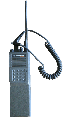
Motorola MTX900 portable radio. Most of these radios were used by municipalities and utility companies. They could be missing knobs, antennas, have engravings, and possibly cracked housings. However, due to rugged design, the internal components are usually not damaged. Housings, knobs, batteries, and chargers from Genesis series: P200, HT600, MTX800, MTX810, MTX820, and MT1000 radios will work with the MTX900. Front covers of Genesis series radios are interchangeable. Internal speaker components and connections are different on some models. The 900mhz antenna is not interchangeable with other Genesis radios due to frequency range. Some models had keypads as shown in the photo. Trunked systems using phone interconnects required the keypad. Radio must be capable of conventional AND trunked modes. Some MTX900 models were capable of only trunked mode are useless for conventional use/monitoring. The radio shown has its discriminator audio ported out the accessory connector and through a modified speakermic cable. A small mono male plug connects to the sound card line input. |

|
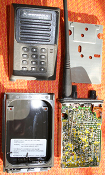
Four machine screws are removed when disassembling the radio. Two machine screws in the metal base are loosened but not removed during disassembly and reassembly. Highly recommend checking hole alignment of housing and front cover before fully tightening any screws. |

|
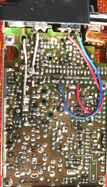
MTX900 circuit board before modifications. This view is looking at the back of the radio with shield removed. Motorola Service manual 68P81069C30-O was used as a reference. Count from right side of connector P1, note pin 5 and pins 9-10 are where the discriminator taps will be taken. Pin 5 is from the discrminator output, pins 9-10 are ground. Pins 9-10 are soldered together at the factory. Used a magnifying glass when soldering as the pads are small. |

|
Pins 1 and 2 on accessory connector (top of radio) are used to output signal to a modified speakermic. Photo shows pinout of accessory connector as viewed from top of radio. Since a regular speakermic wouldn't be used on this radio again, foil between (Pins 1-2) was de-soldered and cut with a hobby knife.
 Placed short lengths of heat shrink tubing over lead ends going to accessory connector after photo was taken.
Didn't want exposed conductor wire on blue and red leads to touch circuit board foil or components.
Placed short lengths of heat shrink tubing over lead ends going to accessory connector after photo was taken.
Didn't want exposed conductor wire on blue and red leads to touch circuit board foil or components.The radio's receiver range is 935-941 mhz. Frequencies can be changed with MTX900 Radio Service Software, a programming cable, RIB, and 386/486 computer. Transmit frequencies were disabled during programming as the radio is used only for receiving. |

|
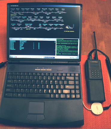
Motorola MTX900, Griffin iMic, and laptop shown in setup used to RX 900mhz ATCS data. Radio's speaker plug was not connected during reassembly since audio is tapped from discriminator. When speaker is connected, data bursts emitted are guaranteed to attract attention and annoy those within audio range even at lowest volume setting. |
|
All logos are property of their respective owners.
Not responsible for any damage to equipment modified using content and/or instructions contained on this page.
This page intended for hobby purposes only.

|